Intrafraction image guidance and mDIBH in multi-target, single isocenter bilateral breast treatment
Case: Intrafraction image guidance and mDIBH in multi-target, single isocenter bilateral breast treatment.
Overview
A 54-year-old female patient was diagnosed with invasive carcinoma (pT1N3M0, stage IIIC) in the left breast and duct carcinoma in situ (pTisN0M0, stage 0) in the right breast. She underwent radical resection of the left breast, breast-conserving surgery for the right breast and chemotherapy. In addition, postoperative radiation therapy was prescribed to deliver 50 Gy to the left clavicle area, 50 Gy to the left chest wall and 50 Gy to the right breast in 25 fractions using single isocenter 6 MV VMAT.
Technique
In appropriately selected candidates, GKRS provides excellent local control while minimizing the neurocognitive toxicity associated with whole brain radiation therapy. The ability to deliver fractionated radiosurgery allows for effective tumor control while minimizing toxicity, particularly for large tumors or tumors abutting critical structures. Because less healthy tissue is affected, patients can have fewer side effects during and after treatment, such as headaches, fatigue, nausea, decreased appetite, hair loss and progressive neurological symptoms. There is also potential for reduced late effects, including neurocognitive impact, endocrine deficits, craniofacial growth changes, hearing loss and secondary malignancy.
Treatment planning
With the patient in mDIBH, a three-dimensional CT scan was obtained with the relative position of the chest wall fixed. Each CTV was outlined on this CT simulation positioning image, and then expanded by 3 mm to obtain the PTV.
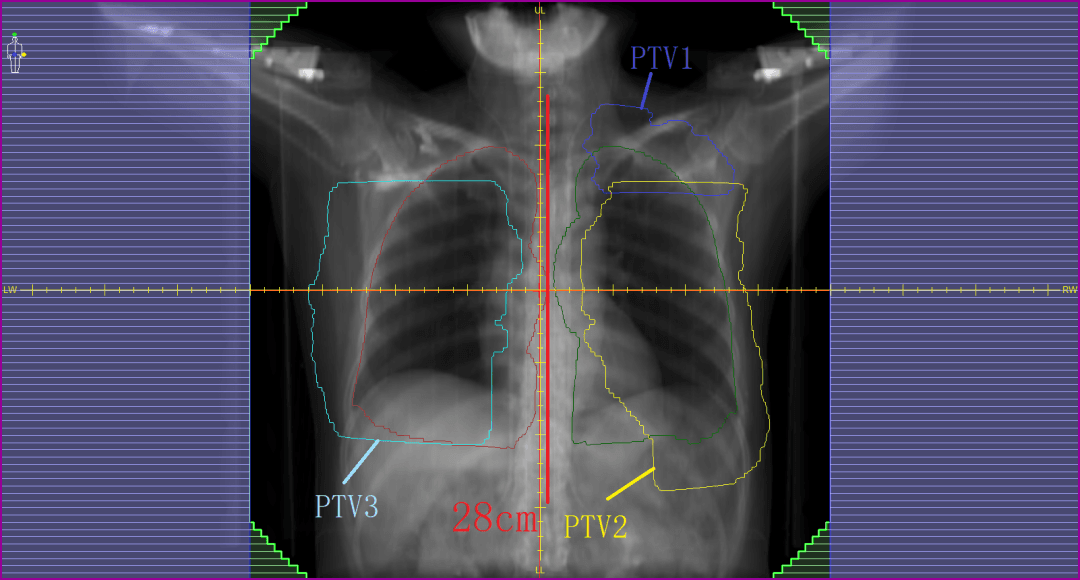
The target area, including the bilateral breast and left supraclavicular area, had a maximum width of 32 cm and a maximum length of 28 cm (figure 1). It was decided to irradiate all three targets simultaneously using a single-isocenter plan in order to reduce the number of set-ups required; to minimize error introduction caused by bed shifts; to avoid the challenge of connecting multiple plans; and to improve patient convenience. Consequently, this treatment required a large treatment field with as large as possible intensity-modulated field range. The MLC would be required to form over-isocenter subfields simultaneously, including dynamic intensity-modulated subfields 15 cm beyond the midline, with sufficient modulation to achieve plan objectives.
This treatment would be delivered using the Elekta Infinity linear accelerator with the Agility MLC. Agility has 160 x 0.5 cm MLC leaves, which cover a large 40 cm x 40 cm field. The maximum leaf speed for this MLC is 6.5 cm/s and, with dynamic leaf guides, leaf travel extends to 15 cm over the midline (figure 2). Agility also has dynamic orthogonal tungsten jaws that can travel 12 cm over the midline (figure 3) and can reach speeds of up to 9.0 cm/s, also dynamically shielding portion of the outer segment leaves to increase the resolution and dose gradients at the edge of the treatment fields.
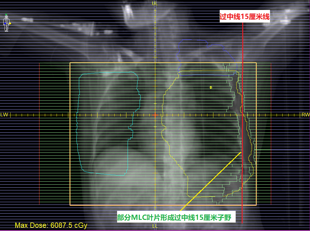
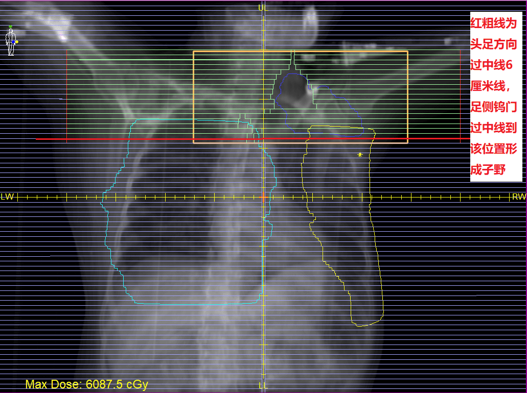
Using the Monaco Monte Carlo planning system, a 6MV FFF VMAT plan was designed to improve treatment efficiency and plan quality.
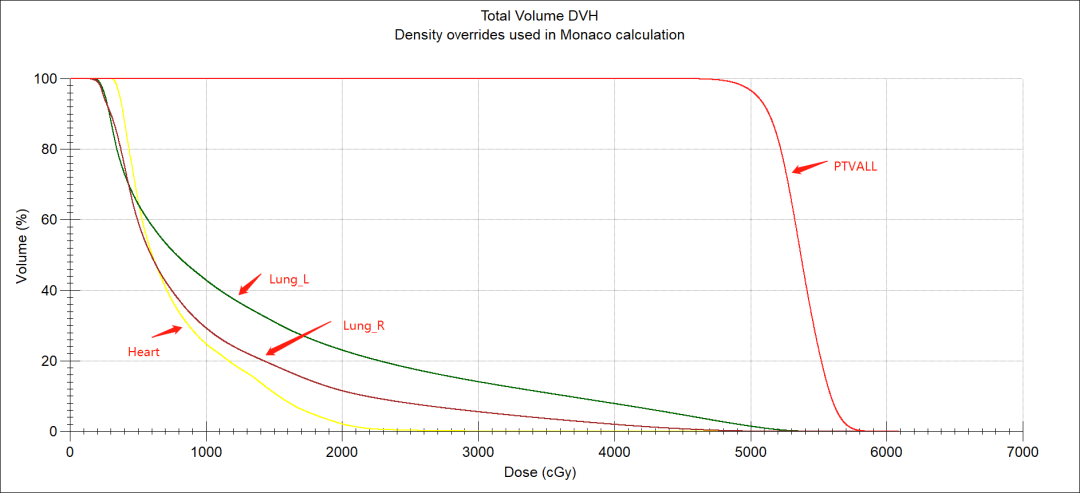
The PTV was divided into the left supraclavicular target area (PTV1), the left chest wall target area (PTV2), and the right breast target area (PTV3). Three arcs were used for each beam with two rotations. The sampling increment of each arc was set to 10° and, according to the target zone position, set the VMAT arc amplitude angle. For PTV1, the gantry moved clockwise from 300° to 120°; for PTV2, the gantry moved clockwise from 300° to 150°; for PTV3, the gantry moved clockwise from 220° to 70°. Finally, the results were optimized to meet clinical requirements. The lungs and heart were well protected (figures 4-5, tables 1-2).
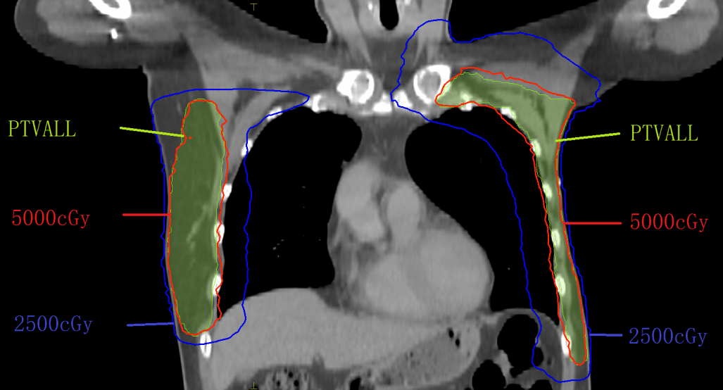

| Prescription/constraints | Actual plan | ||
| Target | PTV | 5000 cGy/25# Cover 95% volume | 5000 cGy/25# Cover 96.65% volume |
| Critical structures | L lung | V5 <65%, V20 <25% | V5 <64.51%, V20 <23.00% |
| R lung | V5 <65%, V20 <25 | V5 <59.51%, V20 <11.48% | |
| Heart | Dmean <900 cGy | Dmean <792.9 cGy | |
Table 2. Comparison of clinical prescription requirements and actual plan results for bilateral breast VMAT plan.
Quality assurance
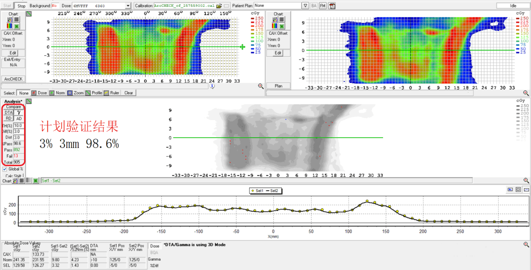
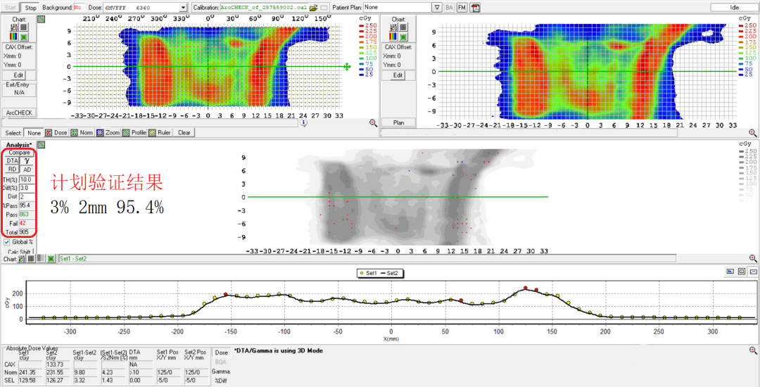
Arccheck dose verification demonstrated a 98.6% pass rate at criteria of 3% and 3 mm (figure 6) and a 95.4% pass rate at criteria of 3% 2mm (figure 7).
Treatment delivery
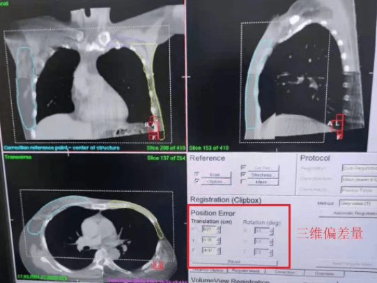
With the patient in mDIBH, an XVI rapid imaging scan (CBCT) was obtained as the gantry rotated from 315° to 165° at 360° per minute for a total of 35 seconds during two 30-second breath holds. Couch adjustments were made automatically to correct the patient's treatment position prior to initiation of radiotherapy (figure 8).
The patient was treated during mDIBH using ABC and the Response gating interface. Intrafraction imaging was used to monitor patient position in real time to ensure accurate treatment delivery (figure 9).
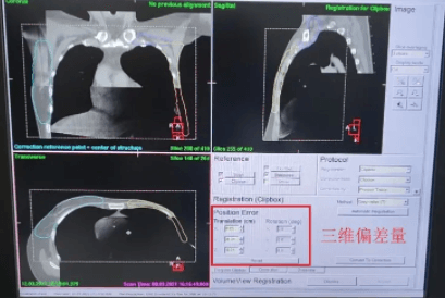

3D-CBCT image registration and intrafraction imaging showed that target position deviated less than 1 mm in all directions (table 3), confirming that the target area was accurately controlled. The use of BodyFIX and ABC for mDIBH effectively controlled the patient’s respiratory motion and involuntary movements during treatment, allowing all target areas to be expanded by a PTV margin of only 3 mm.
Discussion and conclusions
The physical capabilities of Agility greatly improve the dose sculpting ability of VMAT. The dynamic orthogonal jaws, described above, allow virtual 1 mm leaf width precision, which helps increase the potential dose gradient around the target area and spare organs at risk.
The HexaPOD robotic couch provides precise six-dimensional patient positioning, with a translational error correction accuracy of 0.2 mm, and a rotational error correction accuracy of 0.2 degrees. At the same time, the segmented image-guidance technology ensures the accuracy of patient position during treatment delivery, reducing the risk of dose deviations caused by patient movement.
With the patient in mDIBH during imaging and treatment, the chest cavity expands, increasing the distance between the chest wall and the heart. For breast cancer patients, this can effectively reduce irradiation of the heart and lungs, thus minimizing the risks of radiation induced later side effects. mDIBH also ensures that the relative position of the patient’s internal anatomy is fixed during treatment to enhance the accuracy of radiotherapy delivery. Intrafraction image guidance demonstrated that the use of BodyFIX and mDIBH effectively controlled patient respiratory motion or involuntary movement during treatment, so that all target areas were expanded by a PTV margin of only 3 mm. This maximizes protection of normal tissues outside the bilateral breast target area to improve quality of life for the patient.